
The Instrument
Design Overview & Implementation
The science goals of POLLUX lead to the following technical requirements:
| Parameter | Requirement | Goal | Reasons for requirement |
| Wavelength range | 90 - 400 nm | 90 - 650 nm | 90 nm to go down the Ly series 400 nm to reach Ca II lines |
| Resolving power | ≥120,000 | ≥200,000 | Resolve ISM line profiles, Solar System and Cosmology science cases |
| Length of a spectral order | At least 4 nm | ≥ 5 nm | To avoid having broad spectral lines spread over multiple orders |
| Polarisation mode | Circular + Linear (IQUV)Circular + Linear (IQUV) | Magnetic field measurements Geometric shapes | |
| Polarisation accuracy | 10-4 | 10-6 | Detect weak stellar magnetic fields (10-4); measure the fields of hot Jupiters (10-6) |
| Observing modes | Spectropolarimetry and pure spectroscopy | Optimize SNR as a function of science cases | |
| Radial velocity stability | Absolute = 1 km/s and relative = 1/10 of pixel | Absolute for line variations; relative to avoid spurious polarization signature | |
| Flux stability | 0.1% | Probe flux and polarization correlation in WDs | |
| Calibration | Dark, bias, flat-field, polarization and wavelength calibration | Flux calibration | Flux calibration for spectroscopy is classic, but effective procedure is yet to be defined for spectropolarimetry |
These high-level requirement drive the architecture and design solutions. Note that we adopted the telescope parameters
provided by the LUVOIR study team.
The baseline configuration of POLLUX presented here allows fulfilment of all the requirements for the instrument performance needed to reach the science goals.
Most of the technologies required for a complete implementation present technology readiness levels (TRLs) compatible with a Phase 0 study. We did not find fundamental
restrictions or physical limitations preventing its implementation. We will discuss what research and development (R&D) is needed to allow us to realize the baseline
configuration by the time of LUVOIR implementation.
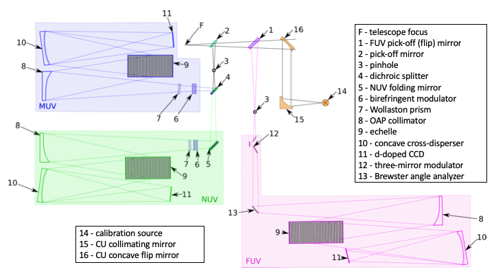
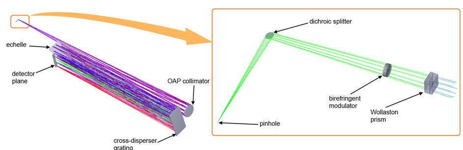
• The instrument entrance is a pinhole, rather than a slit, for simpler aberration correction.
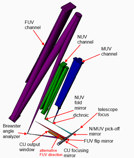
• The working spectral range is 90 to 400 nm. Splitting into three channels allows to achieve high spectral resolving power with feasible values of the detector length, the camera
optics field of view, and the overall size of the instrument. It also allows us to use dedicated optical elements, coatings, detector and polarimeter for each band, hence to obtain
a gain in efficiency.
• The FUV and MUV boundaries are set relative to the Lyman-α line. The lower limit for the MUV band is set at Lyman-α minus roughly 3 nm, that is 118.5 nm, while the upper one for
the FUV is Lyman-α + roughly 3nm, i.e. 124.5 nm. Hence, Lyman-α is always observed (at redshift zero), whatever the POLLUX mode.
• The shortest wavelength for the FUV strongly depends on the main telescope throughput and may be reconsidered in the future. The current design was developed for the lower limit
equal to 90 nm.
• In order to reach as high performance as possible, POLLUX uses two pick-off mirrors with optimized coating for the FUV and MUV+NUV channels, respectively.
• The FUV pick-off mirror is coated with SiC. In the telescope beam, it is located right in front of the MUV+NUV pick-off mirror, but is mounted such that it can be rotated off the beam,
when the FUV channel does not need to be fed (see Fig. 2).
• The MUV+NUV pick-off mirror is coated with Al+MgF2.
• The instrument entrances are pinholes, rather than slits, for simpler aberration correction, and better polarimetric stability. Also, it allows rotation of each channel with
respect to the chief ray.
• The MUV and NUV channels are separated by means of a dichroic splitter. Such splitters can have a high efficiency. The dichroic splitter allows the instrument to work
in two bands simultaneously and use the full aperture thus achieving the high resolving power with relatively small collimator focal length. In the present design, we set the MUV/NUV
boundary at 200 nm, to have a maximum of one full octave in the NUV channel.
• The polarimeters are placed as close to the focal point as possible to reduce their size and influence on the image quality. The NUV and MUV polarimetric units are placed 30 mm
away from the pinhole. For the FUV the distance is 20 mm.
• In each channel the beam is collimated by an ordinary off-axis parabolic (OAP) mirror. The off-axis shift and the corresponding ray deviation angle are chosen in such a way that
the distance between the entrance pinhole and the echelle grating is large enough to place the polarimeter and corresponding mechanical parts. The MUV and NUV mirrors have slightly
different geometry to provide the necessary sampling per pixel. They also have different orders separation and, subsequently, different cross-disperser diffraction and blazing
angles
• Echelle grating works in a quasi-Littrow mounting. The exact values of the groove frequency and the blaze angle are computed to obtain the target dispersion and subsequently the
required spectral resolving power.
• The cross-disperser in each channel operates also as a camera mirror, so it is a concave reflection grating. This approach allows minimization of the number of optical components
and increases the throughput. In order to correct the aberrations, the cross-disperser is a complex pattern of grooves formed by holographic recording. Each of the gratings is
recorded by interference of two beams. One is collimated and another is aberrated by a customized freeform mirror. It allows to correct the aberrations over the extended linear
field. The beams are oppositely directed, so it is possible to obtain triangular grooves with the necessary blazing angle without additional processing like ion-beam etching.
The MUV and NUV camera parts are similar, which facilitates the manufacturing, testing and assembly.
• Adopted coatings on the optical elements of POLLUX are those used for the telescope, except for the polarizers. In the future, they will be optimized for each element of each
channel.
• Polarimeters are located immediately after the splitters in each channel to avoid instrumental polarization by the spectrograph elements. The polarimeters are retractable in the
MUV and NUV to allow the pure spectroscopic mode. In the FUV only the modulator is retractable. The analyzer is kept in the optical path to direct the beam towards the collimator.
• Change of the optical path caused by removing the polarimeter from the beam is compensated by replacement of the collimating mirror. In each channel two OAP mirrors are mounted
next to each other on a translation stage.
• The polarimeter design was optimized for each channel accounting for the technological feasibility. The polarimeters have the minimal size in order to decrease their influence
on the image quality. Firstly, transparent plates introduce some aberrations. Secondly, due to polarization ray splitting the collimator may operate in an unusual mode and have
considerable aberrations. Thirdly, the shorter the optical path inside the polarimeter, the smaller the difference between the spectropolarimetric and the pure spectral observation
modes.
• Spot sizes close to the detector center are 16 x 40 μm for the NUV, 50 x 60 μm for the MUV, and 20 x 28 μm for the FUV. The second dimension corresponds to the order separation
direction. It may be increased to simplify the aberration correction, since it does not affect the spectral resolution.
It is necessary to switch beams in POLLUX in order to feed the detectors with light coming either from the telescope, or from sources in the calibration
unit.
Furthermore, in order to compensate the optical path difference and maintain the same beam position and the angle of incidence at the echelle when switching from the
spectropolarimetric mode to the spectroscopic mode (done by removing the polarimeters from the optical train), it is necessary to change the collimator mirror.
Due to the focal length change, the collimated beam and therefore the theoretical resolution limit are also changed. On the other hand, the pinhole projection size is also changed,
so the resolution values found with account for the aberrations is re-scaled.
The polarimeters
Each channel (FUV, MUV and NUV) has its own specific polarimeter in order to increase polarimetric performances. All polarimeters use temporal modulation. Each polarimeter is then divided in two components: a modulator and an analyzer. The modulator is rotating around the optical axis and rotates the polarization of the incoming light. The analyzer is a linear polarizer that filters the light in a fixed position. By rotating the polarization and filtering it, we create a temporal modulation which allows us to measure the input polarization. We use polarimetric efficiencies to characterize the performances of the polarimeters. We remind that to extract all Stokes parameters at the same time, efficiency optimum is at 57.7% for each Stokes parameter.
NUV polarimeter
MUV polarimeter
FUV polarimeter
